IoT Switches (DEBUG)
Home Assistant Smart Switches (DEBUG)
Having recently set up Home Assistant, I aimed to fully automated my home by progressively converting the light switches to IoT-enabled switches, allowing me to control them remotely via my phone or Google Home. In order to achieve this, I designed and printed a circuit to fit inside the common UK socket boxes.
The schematic and board files can be found here.
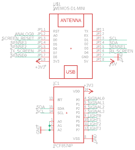
Overview of circuit: The ESP8266 was chosen as the core microcontroller of the project due to its low-cost and ease of integration into ESPHome (Home Assistant). However since the ESP8266 did not have sufficient GPIO pins, a PCF8574 was used to expand the number of GPIO available. Currently the pinouts of GPIO on the ESP8266 and the PCF8574 are as follows:
| Pin | Board | Function |
|---|---|---|
| D8 | WeMos | Button 0 |
| D3 | WeMos | Button 1 |
| D6 | WeMos | Button 2 |
| D5 | WeMos | Button 3 |
| P0 | PCF8674 | Relay 0 |
| P1 | PCF8674 | Relay 1 |
| P2 | PCF8674 | Relay 2 |
| P3 | PCF8674 | Relay 3 |
| P4 | PCF8674 | Light 0 |
| P5 | PCF8674 | Light 1 |
| P6 | PCF8674 | Light 2 |
| P7 | PCF8674 | Light 3 |
Therelay setup controlled by the PCF8574 is as follows:
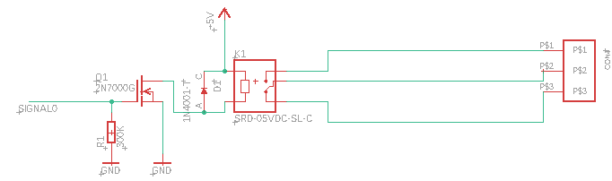
I used a simple transistor setup without an optocoupler as there was limited space on the board and I assumed that the galvanic isolation from the relay would be sufficient. Moreover, I added a flyback diode across the relay to ensure that current spikes from the inductive effect of the relay coil would be dissipated.
As for the physical buttons that would control the switches from the hardware itself, I ordered small 16mm buttons that would sit in a 3d printed case to be mounted in place of the existing switch panels of the UK switch socket box. Files to the entire project will be available soon!
The relays I used were SRD-05VDC-SL-C purchased of AliExpress with a voltage and current rating of 10A @250 VAC.
To power this entire setup, I used an inexpensive transformer unit AC-DC 5V 700mA Transformer Power Supply Unit. I have used this transformer unit to power other projects before and they have worked well with no noise on the output leading to unexpected results on ESP8266s. The mains source for these power supplies was routed in from another nearby power source so that I could turn off the entire setup without having to turn off the entire lighting circuit of that room.
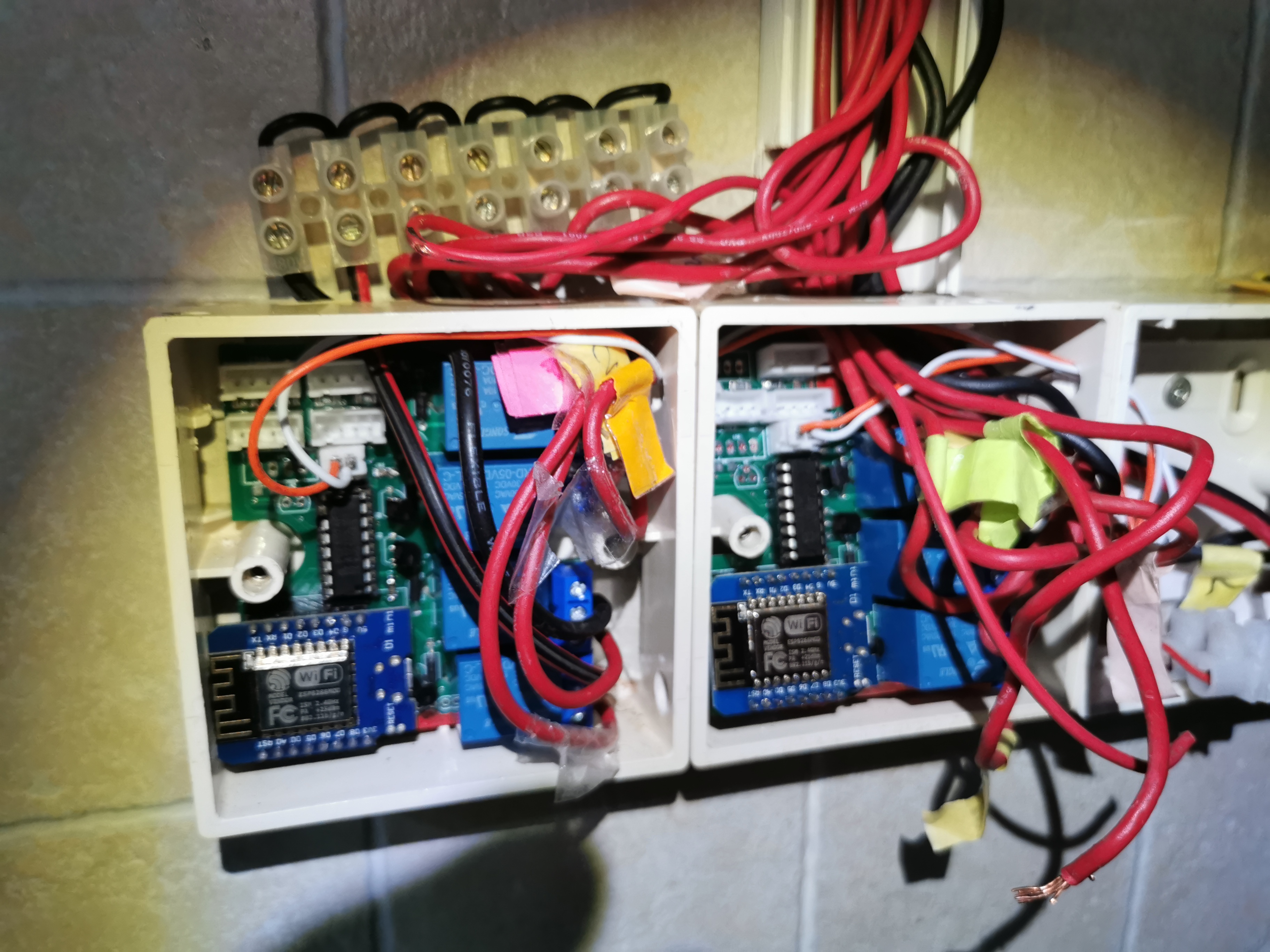
The entire setup is installed in the socket box as shown:
Pre-trials In order to test the working functionality of the relays before I added it into the switchboxes (to save me some time), I tested each switch individually with an old toilet light fixture that had 2 Phillips PL-C 2-pin fluorescent light bulbs.
I tried cycling through each relay individually many times and often very quickly to sniff out any problems that would should have manifested itself with individual relays. I didn’t try all the relays at the same time as I did not have enough devices to connect to all 4 relays of the board.
The pre-tests showed that everything was working fine and the individual relays were able to sequentially turn this load on and off. What was also interesting here (commenting with retrospect) was that the bulbs in this setup were almost identiical to the light fixture that produced problems later on… making this extremely perplexing.
Initial field trials and troubleshooting On first trial without any load, both the buttons and the relays were operating normally. However, problems arose when the load was connected:
In the video, I cycle through the switches using the Home Assistant interface with ESPHome. Noticeably, the relays worked fine for LED light fixtures, however when turning off fluorescent lights (the yellow set of lights at 0:28 of the video), the all the relays (and thus lights) were suddenly turned on. Upon checking the Home Assistant logs, no logs on the state of the other switches changing was logged. Moreover, the swithches in the interface were also in the “OFF” state. Therefore it was very likely that the PCF8574 output pins were pulled high from the action of turning off the relays of the flourescent lights.
At the moment the following suspicions and thus remedies are presented (in order of likelihood):
-
The PCF8574 glitches out when fluorescent lights are switched off on the relay. The cause behind this is unknown as I lack a proper oscilloscope and the know-how to troubleshoot the PCF8574. Solution: Redesign the board and switch the relay pins to the ESP8266 and leave the PCF8574 to do the sensing on the button and the outputs on the light
-
Magnetic interference caused by the tangled nature of the wires could be causing the PCF8574 to glitch out. Solution: Better wire management (which has been done, greatl reducing the amount of wire clutter); possibly isolating the wires from the circuit board using an aluminium foil?
-
Lack of isolation between load circuit and signal circuit. Solution: Redesign the board with optocouplers to switch the relay with a separate power supply for the relays and the IC components.
I have reached out to forums for help regarding this weird behavior of the relays and will update this page (or start a new post) as soon as I get any leads on solving this issue.