Wireless Doorbell with Blynk
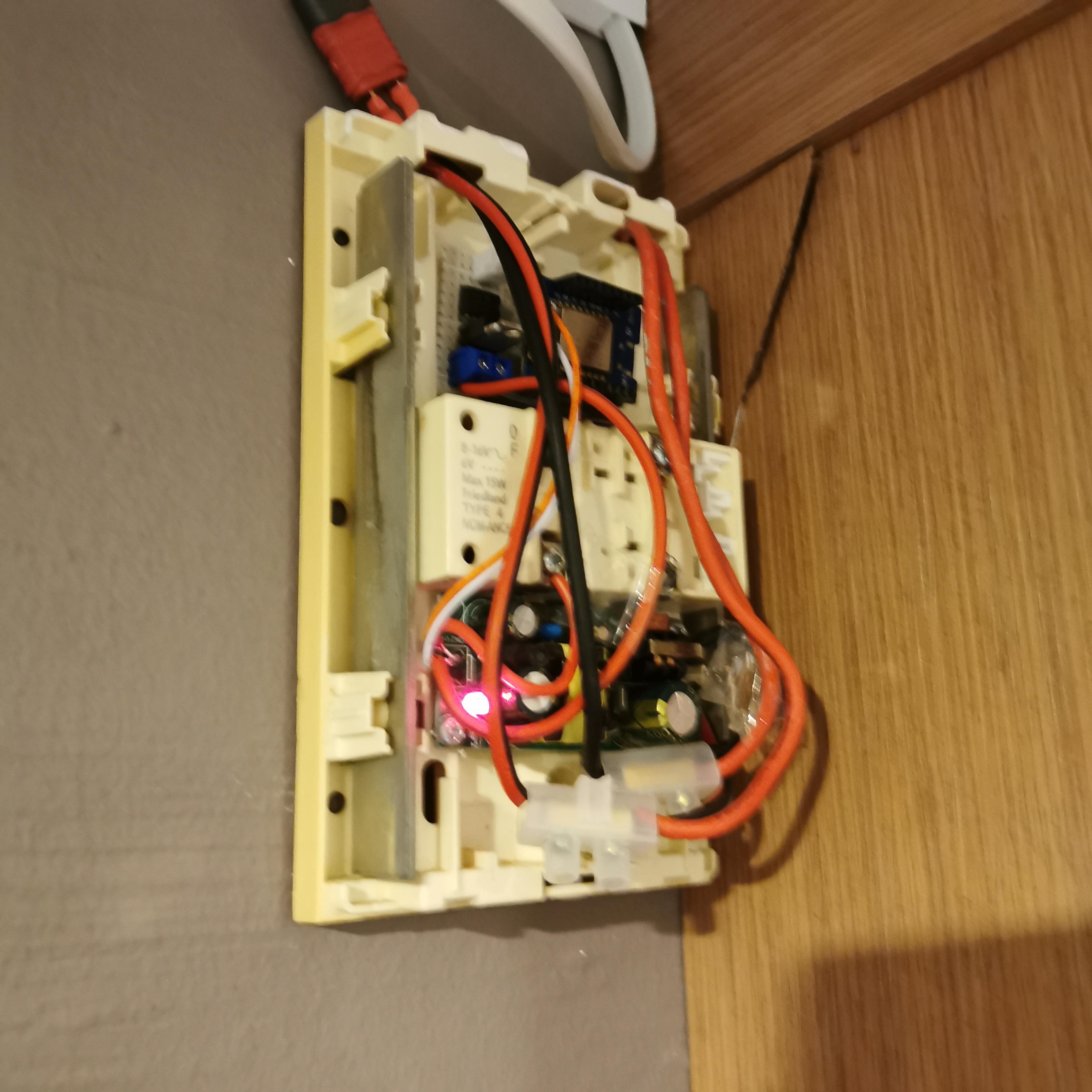
Over-Engineered Doorbell in all its Glory:
Recently I have been working on implementing an over-engineered doorbell for the purposes of
- Allowing for muting of the doorbell via app
- Allowing for push notification to my phone when someone rings the doorbell (just in case I am not able to hear it)
- Most importantly, allowing me to trigger the doorbell remotely via my app when I am outside
But before everything else, a bit of context: My current doorbell is a rather old design that actually uses a mechanical switch to manually open and close a circuit to a solenoid. This meant that there was a wire running from inside the house to the outside switch box where the doorbell switch was located. This was really what spurred me to convert my doorbell to wireless as repurposing this wire (which was literally a standard multi-core copper wire) to transmit power rather than signal was something which would allow me to power the WiFi chip directly via the mains instead of having to deal with batteries (something I try to avoid as much as possible especially when we are dealing with WiFi). But before everything else, a bit of context: My current doorbell is a rather old design that actually uses a mechanical switch to manually open and close a circuit to a solenoid. This meant that there was a wire running from inside the house to the outside switch box where the doorbell switch was located. This was really what spurred me to convert my doorbell to wireless as repurposing this wire (which was literally a standard multi-core copper wire) to transmit power rather than signal was something which would allow me to power the WiFi chip directly via the mains instead of having to deal with batteries (something I try to avoid as much as possible especially when we are dealing with WiFi). As such, the first step I took was to route a connection from a mains socket to the current doorbell after which I connect the mains wiring to the doorbell wire, bringing it live.
Subsequently, I added a Switch Mode Power Supply unit to the live wire at both the doorbell end and at the doorbell switch end to convet the mains voltage to 5V DC voltage that my development board (WeMos D1) could use. For the doorbell, I had to use a power supply with a larger amp rating. More on that later. Now I had to figure out how the doorbell actually worked (and consequently whether I was able to use the 5V DC supply to power the doorbell). It turns out the doorbell’s operating mechanism was rather simple. The doorbell was initially powered via 4 C Size batteries, bringing the total voltage to 4 * 1.5V = 6V. At it’s core of the setup was a solenoid which was connected to two terminals (1 and 2). The other two terminals were connected to the terminals of the battery. When the switch was pressed, the circuit was closed and the solenoid was energized via the batteries, causing it to exert a force on the two chimes, creating the tone. As such, it was quite clear that I would need emulate the physical switch (most likely with an electronic switch), ie a MOSFET or a BJT. Eventually I chose to go with a MOSFET as it could switch high currents with ease with a minimum On current (as compared to BJTs). This was also the reason why I chose a beefier SMPS power supply as from the lab bench PSU the current drawn was about 0.8A. With that, I set about designing the circuit in AutoDesk EAGLE (just for reference) because the project was too small for a PCB to be manufactured. I mainly stick to low cost perf board for such one time use applications.
Lastly, the board I will be using will be the WeMos D1 Mini which is a cheap and neat breakout board that is based of the low-cost ESP8266 WiFi chip. Such a board is rather common and inexpensive, however it lacks certain key features such as multiple Analog I/O (it only has 1 A0 pin at 3.3V) and the entire setup is also a 3.3V logic level board (which makes interfacing a bit more challenging especially for digital sensors [since often 5V logic level boards can interpret 3.3V but not vice versa as 5V will destroy a 3.3V board]) For the software I will be making use extensively of Blynk as it is open source and free (for the most part until you run out of energy). The overall schematics are as follows: I wrote some sketches in Arduino IDE for the WeMosD1 mini (after installing the required boards under board manager and the Blynk Library in the Libary Manager).
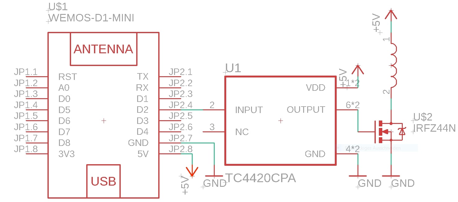
Schematic for the actuator:
Sketch for the actuator:
Coming soonFor the actuator, the integration is rather simple. The basic flow goes like this:
- Receive data from BLYNK_WRITE() and if it is 1 (high), toggle the state of the doorbell to high
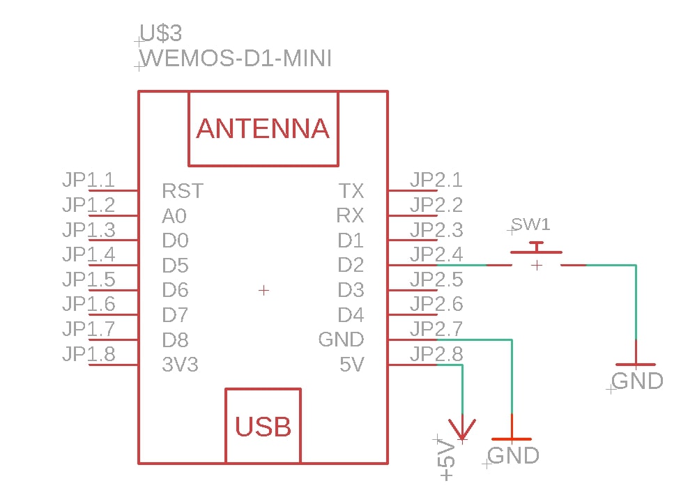
Schematic for the Switch
Sketch for the Switch:
#include <ESP8266WiFi.h>
#include <ESP8266mDNS.h>
#include <WiFiUdp.h>
#include <ArduinoOTA.h>
#include <ESP8266WebServer.h>

ESP8266WebServer server;

#include <BlynkSimpleEsp8266.h>
char auth[] = "My Blynk Auth Code";

#ifndef STASSID
#define STASSID "My Wifi SSID"
#define STAPSK "My Wifi Password"
#define DEBUG_ESP_OTA true
#endif

const char *ssid = STASSID;
const char *password = STAPSK;

WidgetBridge bridge1(V1);
BlynkTimer timer;

boolean ota_flag = true;
const char buttonPin = 4;
int debounceDelay = 200;
boolean initialState = false, finalState = false, buttonState = false, virtualState = false, virtualLastState = false, mute = false;
uint16_t time_elapsed = 0;
uint16_t debounceTimer = 0;

BLYNK_CONNECTED() {
  bridge1.setAuthToken("My other Auth Code"); // Place the AuthToken of the second hardware here
}

void yourSetup()
{
  Blynk.begin(auth, ssid, password);
  pinMode(buttonPin, INPUT_PULLUP);
  //timer.setInterval(500L, printStatus);
}

void setup()
{
  Serial.begin(115200);
  Serial.println("Booting");
  WiFi.mode(WIFI_STA);
  WiFi.begin(ssid, password);
  while (WiFi.waitForConnectResult() != WL_CONNECTED)
  {
    Serial.println("Connection Failed! Rebooting...");
    delay(5000);
    ESP.restart();
  }

  // Port defaults to 8266
  ArduinoOTA.setPort(8277);

  // No authentication by default
  ArduinoOTA.setPassword("My Password to Upload Code");

  // Password can be set with it's md5 value as well
  // MD5(admin) = 21232f297a57a5a743894a0e4a801fc3
  // ArduinoOTA.setPasswordHash("21232f297a57a5a743894a0e4a801fc3");

  ArduinoOTA.setHostname("Doorbell Switch");

  ArduinoOTA.onStart([]() {
    String type;
    if (ArduinoOTA.getCommand() == U_FLASH)
    {
      type = "sketch";
    }
    else
    { // U_FS
      type = "filesystem";
    }

    // NOTE: if updating FS this would be the place to unmount FS using FS.end()
    Serial.println("Start updating " + type);
  });
  ArduinoOTA.onEnd([]() {
    Serial.println("\nEnd");
  });
  ArduinoOTA.onProgress([](unsigned int progress, unsigned int total) {
    Serial.printf("Progress: %u%%\r", (progress / (total / 100)));
  });
  ArduinoOTA.onError([](ota_error_t error) {
    Serial.printf("Error[%u]: ", error);
    if (error == OTA_AUTH_ERROR)
    {
      Serial.println("Auth Failed");
    }
    else if (error == OTA_BEGIN_ERROR)
    {
      Serial.println("Begin Failed");
    }
    else if (error == OTA_CONNECT_ERROR)
    {
      Serial.println("Connect Failed");
    }
    else if (error == OTA_RECEIVE_ERROR)
    {
      Serial.println("Receive Failed");
    }
    else if (error == OTA_END_ERROR)
    {
      Serial.println("End Failed");
    }
  });
  ArduinoOTA.begin();
  Serial.println("Ready");
  Serial.print("IP address: ");
  Serial.println(WiFi.localIP());

  server.on("/restart",[](){
    server.send(200, "text/plain", "Restarting...");
    delay(1000);
    ESP.restart();
  });

  server.begin();
  yourSetup();
}

void loop()
{
  if(ota_flag){
    digitalWrite(2, HIGH);
    while(time_elapsed < 30000){
      ArduinoOTA.handle();
      time_elapsed = millis();
      delay(10);
    }
    ota_flag = false;
    digitalWrite(2, LOW);
  }
  server.handleClient();
  yourLoop();
  delay(10);
}

void yourLoop()
{
  Blynk.run();
  timer.run();
  debounce();
  }
void printStatus(){
  if(virtualState != virtualLastState && !mute){
  bridge1.virtualWrite(V1, virtualState);
  virtualLastState = virtualState;
  Serial.print("Mute Status: "); Serial.println(mute);
  Serial.print("virtual State: "); Serial.println(virtualState);
  }
}
void debounce(){
  initialState = !digitalRead(buttonPin);
  if(initialState != finalState) debounceTimer = millis();
  if(millis() - debounceTimer  > debounceDelay){
    if(initialState != buttonState){
      buttonState = initialState;
      bridge1.virtualWrite(V1, buttonState);
      Serial.print("Button Status: "); Serial.println(buttonState);
    }
    }
  finalState = !digitalRead(buttonPin);
}
BLYNK_WRITE(V0){
  int pindata = param.asInt();
  if(pindata == 1) virtualState = true;
  else virtualState = false;
}
BLYNK_WRITE(V2){
  mute = param.asInt();
}
The sketch for the switch (transmitter) is more complex. This is because I chose to have the doorbell be activated by both physical input (input from the button) as well as digital input (input from software). On hindsight I should have directed the digital input directly to the actuator (since both components are online anyways). This would have reduced the total number of queries made to the boards.
The current flow for the switch looks like this:
- Check the physical state of the switch using a debounce() loop (to reduce interference from jitter)
- If the debounce() loop returns a positive outcome (ie the switch has been triggered), set the physical state to HIGH, else set it to LOW.
- Check the digital state of the virtual button (via software).
-
If this is true (the button has been pressed), set the software state to HIGH, else set it to LOW.
- Check if the software state differs from the current Actuator State of the doorbell. If so, toggle the doorbell state (or let the doorbell state = software state).
- If the condition in 5 is met, set the actuator pin to the Actuator State.
- Repeat Step 5 to 6 on the physical state.
The use of intermediary software and hardware state boolean variables allows us to only set the Actuator State (perform an assignment of Actuator State = Software / Hardware State) only when the software / hardware state is different than the current actuator state. A similar approach would be to set a “Last State” for the Actuator and only write the Actuator pin to the state of the software / hardware state when the Actuator State is different from the Last Actuator State.